LADCP
- PI
Dr. Andreas Thurnherr (LDEO)
- Cruise Participant
Ali Siddiqui (JHU)
Data Acquisition and QC
In order to collect full-depth profiles of horizontal and vertical ocean velocity, two Acoustic Doppler Current Profilers (ADCPs), one facing upward (uplooker) and the other downward (downlooker), as well as a Deep Sea Power And Light rechargeable 48V battery and cables were installed on the CTD rosette. This lowered ADCP (LADCP) system was provided by the Lamont-Doherty Earth Observatory. The LADCP system is self contained, requiring on-deck cable connections to charge the battery and for communicating with the ADCPs. The battery charger was affixed to an elevated cable run in the CTD bay and connected to a long power cord extension terminating on a bench in the wet lab next to the bulkhead door leading to the CTD bay. On the bench, the LADCP data acquisition computer, a Mac Mini, as well as two bench-top power supplies for the ADCPs were installed.
Between casts the LADCP system in the CTD bay was left connected to the (unpowered) battery charger, as well as to the two deck cables leading to the data acquisition computer and to the bench-top power supplies. The male plug of the (disconnected) adapter cable between the battery and the LADCP star cable was dummied up. While the deck cables in the wet lab were permanently connected to the acquisition computer with RS232-to-USB adapters, the corresponding power connectors were left disconnected from the bench-top power supplies. With this setup there is no voltage on any of the LADCP cables on the rosette.
A few minutes before the CTD was moved out of the bay for deployment the battery was disconnected from the charger and connected to the ADCPs via an adapter cable and the star cable, both permanently installed on the rosette. The male connector of the battery charger cable was dummied up. In order to start data acquisition, the instruments were woken up by the acquisition computer, the data from the previous cast deleted from their built-in memory cards, and the instruments were programmed to start pinging. Finally the two deck cables were disconnected from the pig-tails that were also permanently installed on the rosette in order to protect the expensive star cable from unnecessary wear. The deck cables and pig tail connectors were dummied up and the latter were secured to the rosette with a velcro strap to avoid whipping during the casts. Once everything was set up, the CTD operator and/or the marine tech were notified that the LADCP system was ready for deployment. Deployment information was logged on LADCP log sheets either when the data acquisition was started or once the CTD system had entered the water.
After the CTD had been secured in the bay after each cast the velcro securing the dummied up pig-tail ends to the rosette was removed, the dummied up pig-tail ends were rinsed with fresh water, the dummy plugs were removed, and the pig tails were connected to the deck cables. Using the acquisition computer, LADCP data acquisition was stopped after which the data download was initiated. Afterwards the two bench top power supplies were connected to the deck cables in the lab, the battery was disconnected from the adapter cable on the rosette, the male end of the battery adapter cable on the rosette with two exposed pins now carrying 48V (from the bench-top power supplies) was dummied up, and the battery cable was attached to the (still unpowered) charger cable. Afterwards power was applied to the battery charger in the wet lab and the time noted on the LADCP log sheet.
After the data from the cast had finished downloading (after about 20 minutes on deep casts), the bench top power supplies were disconnected from the deck cables in the lab. Then the data files were checked by integrating the measured vertical velocities in time, which yields estimates for the maximum depth (zmax) and the end depth (zend) of the profile, both of which were recorded on the log sheet. After the battery was fully charged (usually about an hour after charging was initiated, as indicated by LEDs on the charger) the charger was disconnected from power in the wet lab and the time was noted on the log sheet. At this stage, the LADCP system was ready for the next cast.
Communication between the acquisition computer and the ADCPs was handled by a new acquisition software (acquire2), implemented as a set of UNIX shell commands designed to minimize the possibility of operator errors. Three different commands are used:
Lstart: This command wakes the instruments, lists their memory contents, clears the memory (after operator confirmation) and programs the instruments to start pinging by uploading command files. CTD station and cast numbers must be provided by the operator since the LADCP files use an independent numbering scheme. (CTD station and cast information, as well as the LADCP profile number were noted on the LADCP log sheet.)
Ldownload: This command interrupts the running data acquisition, downloads the data and backs up the data files to a network drive.
Lcheck: This command integrates the measured vertical velocities from both ADCPs to estimate zmax and zend, which are displayed together with other useful profile statistics before the data files are backed up (again) on the network drive.
While these three commands are all that is needed for LADCP data acquisition, a fourth command (Lreset) is available for resetting the ADCPs after swapping instruments and in case of communications problems, of which there were none during this cruise.
Once or twice a day the LADCP and CTD time-series data were transmitted with rsync to Thurnherr’s lab, where the data were processed for horizontal velocity using the LDEO_IX processing software and for vertical velocity using the LADCP_w processing software. Important diagnostic plots were inspected in the lab, and summary plots for every profile together with a short written assessment was emailed back to the vessel and filed in a ring binder. In addition to these processing diagnostics, LADCP data quality was continuously monitored by creating section plots, some of which can be found in the narrative section of this cruise report. A comprehensive post-cruise LADCP QC will be carried out by Thurnherr in his lab before submission of the new data to the archives.
Instrumentation
A single 300kHz TRDI Workhose Monitor ADCP (WH300, s/n 12734), fitted with a custom self-recording accelerometer/magnetometer package, was installed as the uplooker during all casts. This was the same as used in the first leg (A20). The data from the accelerometer/magnetometer package will be downloaded after the instruments return to the lab and used for QC and final processing if needed.
A second 300kHz TRDI Workhose Monitor ADCP (WH300 s/n 24477) was used as the downlooker during the entire A22 cruise. The same instrument was used for profiles 53-90 in the first leg as well.
While both the ADCPs performed well, there was an error in data acquisition at station 9 and 10. The downlooker ADCP was recording data in two separate files, which indicated a power supply issue during downcast. The issue first appeared at station 9 and persisted in station 10, at which point the non-spillable lead acid battery mounted on the rosette (SN01283) was replaced with a separate fully charged battery. A voltage of 51.3 V was measured using a multimeter before installation. Along with the battery, the star cable along with the deck cable pig tails were also replaced with new ones. It was found that the error was resolved after this operation and both the ADCPs were collecting data in a single file. However, while reconnecting the star cable to the ADCPs, the uplooker and downlooker connections were interchanged which led to the ADCP files of profiles 11-16 being mislabeled (DL instead of UL and vice versa). This issue was subsequently resolved by simply switching the connections of the two serial adapter connectors for the two ADCPs. There were no issues up till station 51, when the uplooker ADCP started storing data in 2 files again. Since there was no data deterioration, it was decided to not change the cables once again, instead a new deck cable along with a battery star cable adapter were kept on stand by in case of any potential issues. The data files for the rest of the cruise were collected for the uplooker ADCP in 2 files. The processing software however, had no issues dealing with it.
Figures
The section plots shown in Figs. 1 & 2 show the zonal and meridional LADCP velocities obtained from the 90 stations occupied.
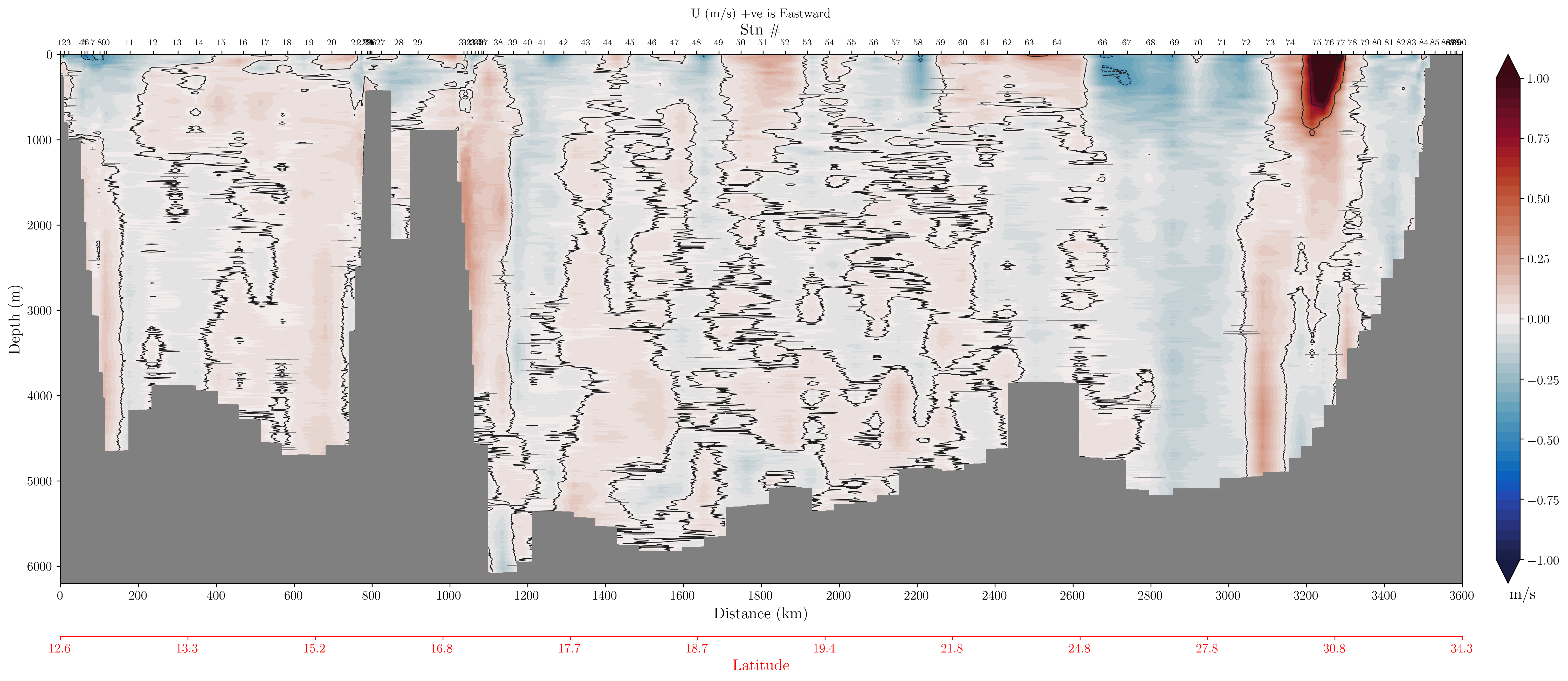
Zonal velocity section for A22 using the LADCP data.
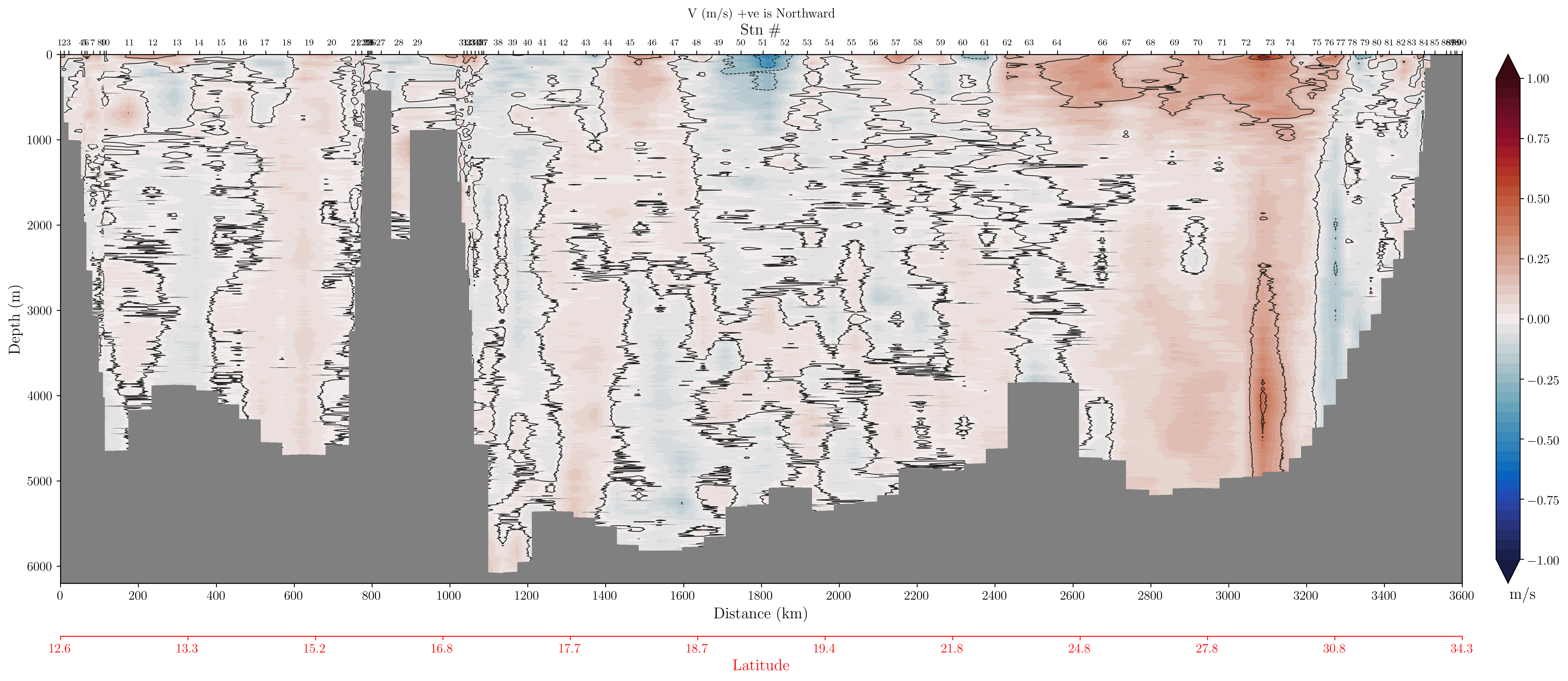
Meridional velocity section for A22 using the LADCP data.